$\require{color}$
Inputs (camera, geometry, lighting, materials) must all be accurate and detailed enough to support.
Reflection by local reflection models such as
Local reflection models: rs between
Global illumination considers all light sources and surfaces, inter-reflections and shadows.
Radiometry: Physical measurement of light/radiation energy
Summary:
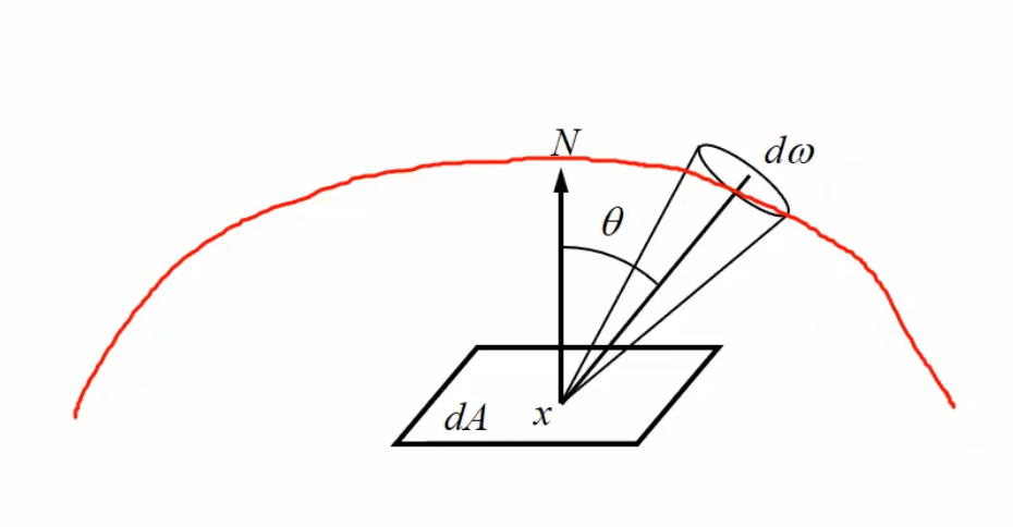
\[\begin{aligned} \text{Radiant Power } \Phi &: \text{light energy over unit time} \\ \text{Irradiance } E &= \frac{d \Phi}{dA} = \text{incident power per unit surface area}\\ &= \int_\Omega L(x \leftarrow \Psi) (N \cdot \Psi) d\omega_\Psi \\ \text{Radiosity } B &= \frac{d \Phi}{dA} = \text{outgoing power per unit surface area}\\ &= \int_\Omega L(x \rightarrow \Theta) (N \cdot \Theta) d\omega_\Theta \\ \text{Radiosity } L &= \frac{d^2 \Phi}{d\omega \cdot dA \cos \theta} \end{aligned}\]Radiant power and radiance:
\[\Phi = \int_A \int_\Omega L(x \rightarrow \Theta) cos \theta d\omega_\Theta dA_x\]Radiance $L$:
Radiometric quantities vary with wavelength, and is perception independent.
Radiance is invariant along straight paths (assuming no medium), and sensors are sensitive to radiance. Together these explain why color/brightness of an object seems to not change with distance.
Emits equal radiance $L$ in all directions.
\[\begin{aligned} B(x) &= \int_\Omega L(x \rightarrow \Theta) \cos \theta d \omega_\Theta\\ &= L \int_\Omega \cos \theta d \omega_\Theta \quad \text{(L is constant.)}\\ &= L \int_{\theta = 0}^{\pi/2} \int_{\phi = 0}^{2\pi} \cos \theta \sin \theta d\theta d\phi \\ & \text{(longitudinal $\theta$, latitudinal (equatorial) $\phi$.)}\\ &= \textcolor{red}{L\pi} \end{aligned}\]Describes the amount of incident light reflected in exitant direction.
BRDF = Outgoing radiance $L$ $\div$ Incoming irradiance $E$
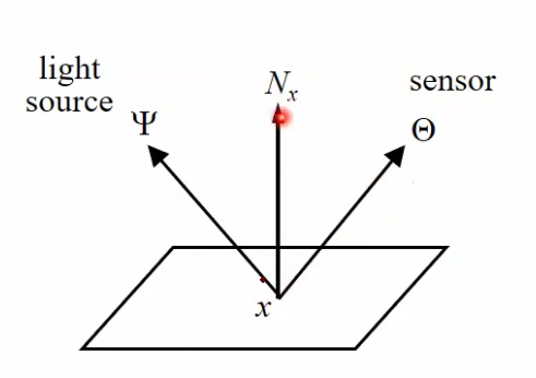
$\Psi$ is incident/incoming light source direction, $\Theta$ is outgoing light.
Implications:
Assumptions:
Range: Any non-negative value
Dimensionality: 4D (incoming and outgoing each contribute two dimensions)
The requirements for physically feasible BRDF are below:
Note about $R$: Occasionally the reflection ray $R = 2(N \cdot \Psi)N - \Psi$ would be included the BRDF. Remember to expand and replace all relevant values.
BRDF is symmetric.
\[f(x, \Psi \rightarrow \Theta) = f(x, \Psi \leftarrow \Theta)\]Total power reflected in all directions must be equal to or less than incident power.
\[\int_\Omega f_r(x, \Psi \rightarrow \Theta)(N_x \cdot \Theta)d_\omega \le 1\]If the BRDF is independent of the incident light $\Psi$’s azimuth angle, it would not include any angle formed by $\Psi$ and any fixed vector (e.g. the tangent of a hair strand.)
Cook Torrance model cannot represent anisotropic (not isotropic) models.
Objects have a plastic-like appearance (diffuse surface + lacquered)
Cannot simulate metallic appearance, where intensity and color of the specular highlights depends on angle of incoming light.
No fresnel effects
The thinner the lobe, the closer to perfect mirror reflection we have, which implies more shininess.
This demonstrates the difference in BRDF when it comes to different wavelengths of light.
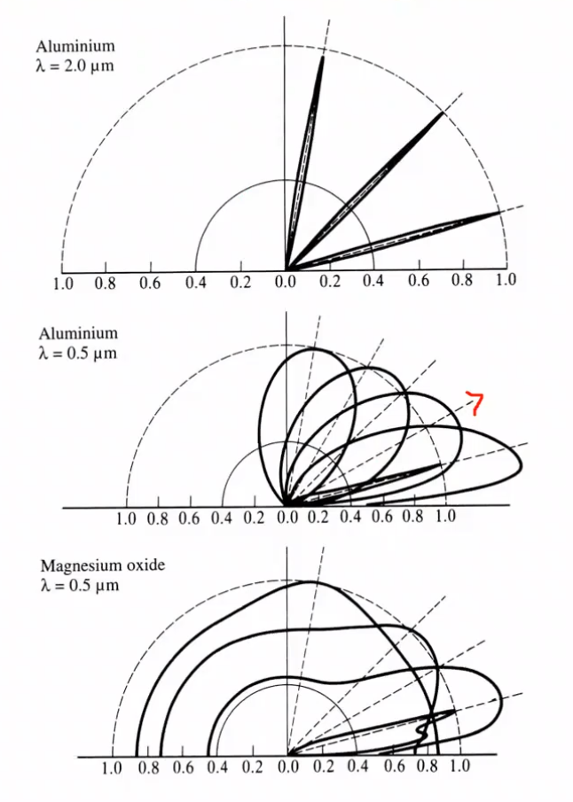
Off specular reflection: the highest intensity may not be at the reflection angle.
The ratio of reflected to transmitted light energy:
\[F = \frac{1}{2} \left( \frac{\sin^2(\phi - \theta)}{\sin^2(\phi + \theta)} + \frac{\tan^2(\phi - \theta)}{\tan^2(\phi + \theta)} \right)\]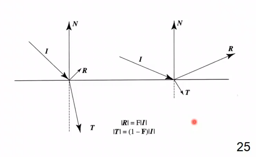
where $f = \frac{(1 - n_1/n_2)^2}{(1 + n_1/n_2)^2}$
Only models the specular component (which is added to the normally computed diffuse model.)
\[f_r(x,\Psi \leftrightarrow \Theta) = \frac{D(\alpha)GF}{(N\cdot\Psi)(N\cdot\Theta)\pi} + \frac{k_d}{\pi}\]$D(\alpha)$: Micro-geometry term
| $\alpha$ is the angle between $N, H$, $H = \frac{L + V}{ | L + V | }$. |
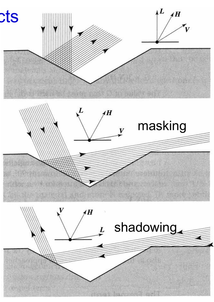
$G$: Shadowing/Masking term
$F$: Fresnel term (see above)
$1/(N \cdot V)$ to account for glare.
(See above) Independent of azimuthal (equatorial) angle $\phi$.
\[f_r(x, (\theta_i, \phi_i) \leftrightarrow (\theta_o, \phi_o)) = f_r(x, (\theta_i, 0) \leftrightarrow (\theta_o, \phi_o - \phi_i))\]